


Controlling AC Devices with the NJA Toolchain
Devices that you plug in a 120VAC wall outlet are not necessarily what you would expect to connect to an Arduino. Most of the beginner-level Arduino projects deal with sensors and small actuators using voltages in the 3.3-5VDC range. But what if you want to use the NJA toolchain (NW.js, Johnny-Five, Arduino) to turn on or off a fan, a smoke machine, a spotlight or anything else that plugs into a regular wall outlet? Is that even possible? Of course it is! To do that, you will simply need four things: a 120VAC device, an Arduino, a relay and this article.
About relays
When we use a wall-connected device, we usually turn it on or off by using a switch built into the device. The switch allows or blocks the flow of current from the wall outlet. If we want to automatically control that same device with an Arduino, we must mimic this behaviour electronically. The component that does that is an actuator called relay. A relay is just like a switch except for the fact that it can be turned on or off by feeding it an electrical control signal instead of using a finger.
As you can see below, the typical relay has two sides. One side (right side in the picture) is for a low voltage input (commonly 3.3VDC or 5VDC) that receives a control signal from another device. In our case, that other device is the Arduino. The other side of the relay acts as a higher voltage switch. When HIGH is applied to the input side, the switch is turned on. When the input side is LOW, the switch is turned off.
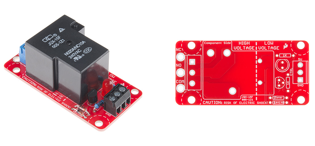
The two sides are completely isolated from one another to prevent the higher AC voltage from ever reaching the Arduino or your computer, which would be very bad.
As you can see from the labels on the higher voltage side, relays can be used in a normally-open (NO) or normally-closed (NC) fashion. By default, a normally-open switch does not let the current go through (because the circuit is open). Therefore, it is OFF by default. The normally-closed switch, on the other hand, is ON by default because a closed circuit means the current is allowed to flow through it.
To flip the switch ON or OFF, you simply need to connect one of the Arduino’s digital outputs to the relay’s control input. Then, when you programmatically set the Arduino’s output to HIGH, the relay interprets it as a “turn on the switch” signal. When you set the Arduino’s output to LOW, obviously, the switch turns off.
Which Relay Should I Get ?
When buying a relay, you have several options. The first option, is to buy only the relay itself and manually take care of all the wiring and soldering. Personally, I don’t think this is worth the trouble so I won’t cover this approach here.
Using a Relay Breakout Board
An easier option is to buy a breakout board which provides you with easy to use screw-type terminals. Examples of such relays are the Sparkfun Beefcake Relay Control Kit (depicted above) and the Keyes Relay Module (depicted in the diagram below). Wiring such breakout boards to the Arduino is quite easy:

The Arduino’s 5V and GND are connected to the matching connectors on the relay. The control signal goes from the Arduino’s chosen digital output (#10 in this case) to the relay’s signal (a.k.a. control) input.
Obviously, you also need to wire the AC higher voltage device. To do that, you will have to make a custom cable to connect to the relay. An easy way to do that is to use an extension cord. This way, you don’t have to cut the cable of the device itself. One end of the custom cable will be connected to the wall and the other end to the device.
To create the cable, carefully cut away the exterior sheathing to reveal the 3 internal wires. Obviously, this needs to be done while the cable is unplugged. Then, cut the hot line and strip the two ends. In North America, the hot line is the black wire. In other parts of the world, it differs.
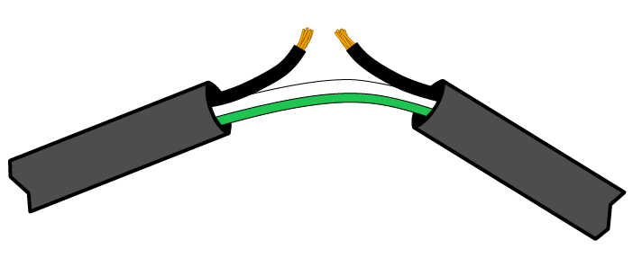
Then, insert one end of the cut wire in the NO terminal of the relay and the other end in the COM terminal. Screw them firmly in place. By using the NO terminal, our switch will be off by default.
If this is too much hassle for you, there is an even easier way…
Using a Relay-Controlled Powerstrip or Inline Switch
The easiest option is to use either a relay-controlled powerbar or inline switch. Basically, in such a case, the relay is pre-wired inside the switch or powerbar. The only thing that remains to be wired is the Arduino’s output to the powerstrip relay’s input. The wiring usually looks like this:
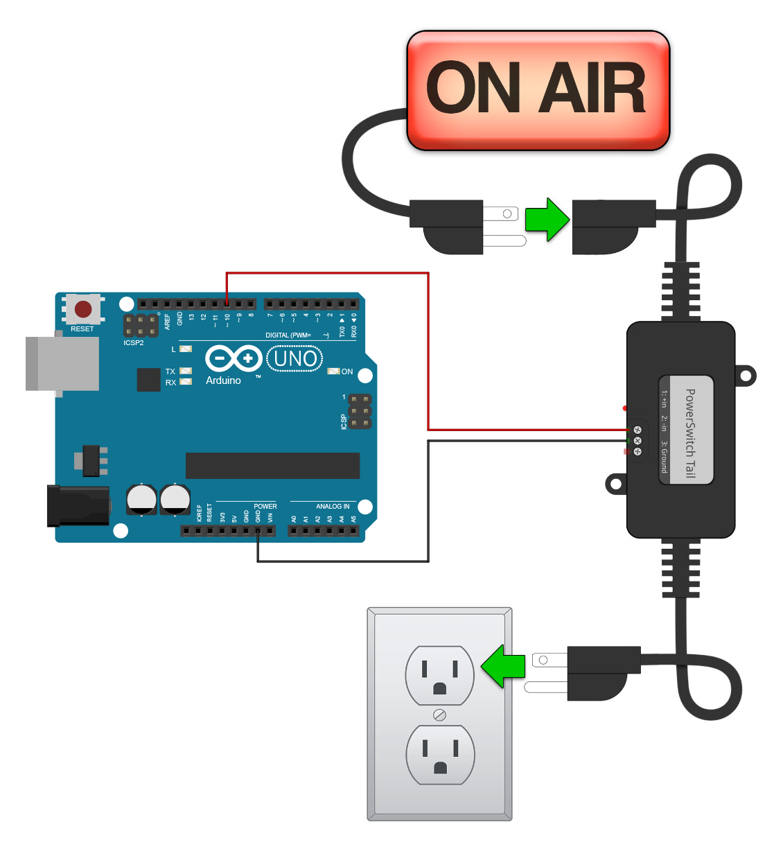
In this setup, the Arduino’s GND is connected to the negative (-) terminal of the inline switch and the digital output of the Arduino (#10) is connected to the positive (+) terminal on the switch. This is a very easy and convenient way to get started.
Safety Warning
If you are not very familiar with how electricity works, you should not use bare relays or breakout modules. 120VAC electricity can be dangerous. The relay-controlled switches and powerbars are much safer options. And, even in that case, be sure to use them in accordance with the manufacturer’s safety instructions. Never touch any part of the relay while its connected to the wall outlet. Never wire a relay while is is connected to AC power.
As a final note on choosing the right relay, you should remember to factor in the device’s current draw. The relays suggested above can support a maximum of 5 to 15 amps depending on the model. As an example, 5 amps is the current drawn by 6 lightbulbs (100W). Be sure you are not using devices with current needs that are higher than what the relay can stand. When in doubt, consult a certified professional.
Let’s Write Some Code
The code to control a relay is amazingly simple. All you need to do is set the output going to the relay to HIGH or LOW. In Johnny-Five, this is easily done by calling the open() , close() or toggle() method of the relay object.
Important update: changes to Johnny-Five 1.1+ broke compatibility with browser-serialport. You should now use chrome-apps-serialport instead. Usage information is available on the project’s GitHub page.
Attention: The code below assumes you are familiar with how to setup an NJA (NW.js, Arduino, Johnny-Five) project. If that’s not the case, please first check out the article titled NW.js, Johnny-Five & Arduino: A Wicked Trio.
|
1 2 3 4 5 6 7 8 9 10 11 12 13 14 15 16 17 18 19 20 21 22 23 24 25 26 27 |
// Fix NW.js' issue with standard input nw.require("nwjs-j5-fix").fix(); // Wait for DOM to be ready window.addEventListener("DOMContentLoaded", function () { // Instantiate J5 library var five = require("johnny-five"); var board = new five.Board(); // Wait for board to be ready board.on("ready", function() { // Create relay object (pin 10, normally open) var relay = new five.Relay({ pin: 10, type: "NO" }); // Toggle the relay's status every second setInterval(function() { relay.toggle(); }, 1000); }); }); |
You don’t even have to have a device connected to try out the code. Relays make a distinctive click sound when they are engaged or disengaged. Therefore you can try the above code first without connecting the device and, when you know the relay works, try again with the device connected. Again: make sure you are not touching the relay while it is connected to the wall.
If you need to use more than one relays, you can use a relay collection. Collections make it very easy to work with several components of the same type.
I hope this is enough to get you started using relays in your project. Remember to be very careful while working with higher voltage AC electricity!
Cheers!
The electrical outlet image used in the header picture is from Isaac Bowen and is used in accordance with the Creative Commons license (CC BY-SA 2.0).